Successfully Implementing Qi Charging: Developer Guide
Wireless charging technology is no longer just a nice-to-have; it is often a decisive competitive advantage. Especially in safety-critical applications, where robustness and reliability are crucial.
However, Qi implementation has pitfalls: Incorrect coil tuning can drastically reduce efficiency, inadequate FOD calibration leads to certification failures, and late test planning causes costly redesigns.
Our Qi guide shows you how to eliminate these risks and develop a market-ready solution.
What you will learn in this article:
- Which Qi profile is optimal for your project
- How to avoid expensive development errors
- The complete certification process step by step
- Proven implementation strategies
What is Qi Charging?
Qi is one of the world's leading standards for wireless charging of devices via inductive energy transfer. The standard was developed by the Wireless Power Consortium (WPC) in 2010 to create a unified, interoperable solution for wireless power supply for smartphones, wearables, headphones, and increasingly embedded devices.
Qi enables a device to be simply placed on a charging station (charging pad) (Figure 1), without plugs, cables, or special alignment. Energy transfer occurs through the principle of electromagnetic induction.
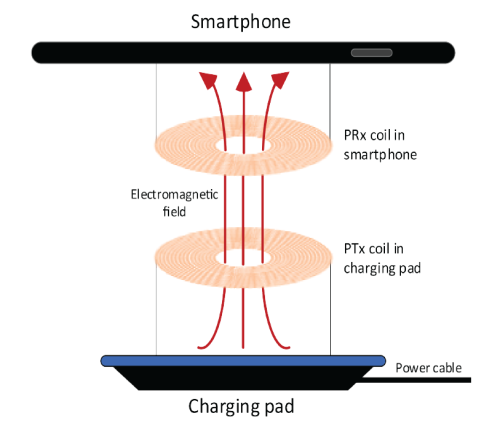
Figure 1: Qi Charging Operating Principle
(Source: Qi-v2.0.1-introduction.pdf, 3.1 Basic concepts)
Advantages of Qi over wired methods:
- Improved User Experience
Simple placement makes charging significantly more convenient than having to find, untangle, and plug in the right cable first. - Higher Product Reliability
Qi charging eliminates the need for repeated plugging and unplugging. This eliminates mechanical wear of connectors. This results in fewer weak points and possibly also more cost-effective housing manufacturing, as no cutouts for connectors are necessary. - Galvanic Isolation
Since there is no physical connection between the charger and the device, galvanic isolation is ensured. This reduces the risk of electrical interference and protects against voltage surges. - Sealed Housings According to IP68
Wireless charging eliminates the need for open or separately protected charging connectors. Ideal for medical devices, outdoor products, or hygiene-sensitive applications.
How Qi Charging Works
The Qi system shown in Figure 2 consists of a transmitter (Power Transmitter) and a receiver (Power Receiver). In the transmitter, an AC voltage is applied to the coil (Lp), creating a magnetic field that is transferred to the receiver coil (Ls) through inductive coupling.
The induced AC voltage is then converted to DC voltage via a rectifier, which is used to power the electronics or charge a battery. The operating principle corresponds to that of a classic transformer, but with the difference that in the Qi standard, active communication also takes place between the Qi receiver and Qi transmitter. This allows, for example, dynamic regulation of power transfer.
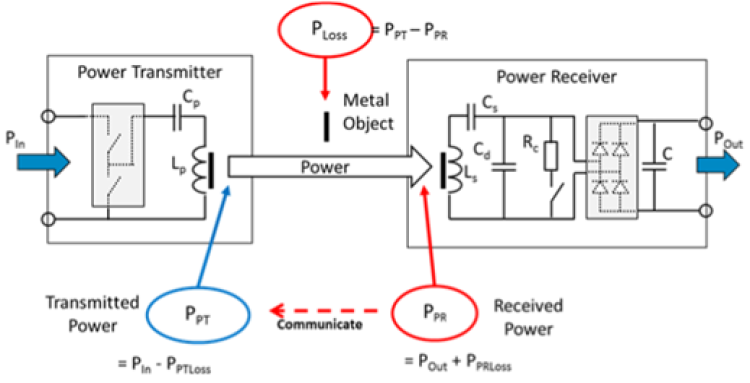
Figure 2: Qi Charging Operating Principle
(Source: Qi-PC0-part1&2-v1.2.3a.pdf, 11.4.1 Introduction)
Intelligent Communication for Optimal Performance
Communication in the classic Qi Baseline Power Profile (BPP) occurs exclusively from receiver to transmitter (unidirectional) and is implemented via Amplitude Shift Keying (ASK). Data is modulated onto the coil signal through targeted load changes on the receiver side.
In Figure 2, this is represented by the resistor Rc. These load changes are inductively fed back from the receiver coil to the transmitter coil and evaluated by the transmitter. Using the communication protocol, parameters such as received power, charge status, foreign object detection (FOD), or termination of energy transfer can be transmitted.
Based on this information, the transmitter adjusts the energy transfer. Power adjustment can be achieved, for example, through frequency adjustment. Reducing the transmission frequency leads to increased power, while increasing the frequency reduces power.
Integrated Safety Mechanisms
- The following safety mechanisms are implemented: Temperature monitoring at the receiver
- Foreign object detection (FOD)
- Protection circuits for excessive currents or voltages
- Communication monitoring
In case of failure, transmission is automatically terminated
(Source: Qi-v2.0.1-comms-protocol.pdf, 8. Power Receiver data packet).
Download the Qi Specifications | Wireless Power Consortium
The 3 Critical Success Factors for Qi Implementation
Choosing the Right Qi Power Profile
When developing a Qi receiver, it is crucial to first determine the appropriate Qi power profile on which development will be based. The various power profiles are briefly described below. Developers starting a new project today should already consider compatibility with Qi2.
The Qi standard is continuously being developed. Originally, everything began with the Baseline Power Profile (BPP), which is designed for a maximum power transfer of 5 watts. For applications requiring higher power transfer, the Extended Power Profile (EPP) was introduced, which supports up to 15 watts. The latest innovation step is the Magnetic Power Profile (MPP), which also offers a maximum transfer power of 15 watts. However, the decisive advantage of MPP lies in the automatic alignment between charger and end device through magnets, leading to easier handling and efficiency improvement.
History of Qi Profiles:
- Qi Profiles up to Version 1.3 (2010 – 2021)
- Baseline Power Profile (BPP)
- Extended Power Profile (EPP)
- Qi2 Profiles from Version 2.0 (2023 +)
- Magnetic Power Profile (MPP)
| Features | BPP (Qi1.x) | EPP (Qi1.x/Qi2.x) | MPP (Qi2.x) |
|---|---|---|---|
| Charging Power | ≤ 5W | ≤ 15W | ≤ 15W |
| Magnetic Alignment | Optional | Optional | Yes |
| Baseline Protocol | Yes | Yes | Yes |
| Extended Protocol | No | Yes | Optional |
| Magnetic Protocol | No | No | Yes |
| Authentication | No | Optional | Optional |
Table 2: Features of Qi Receiver Power Profiles according to
(Source: Qi-v2.0.1-comms-physical-layer.pdf / 1.6 Power Profiles)
Perfect Coil Tuning – The Make-or-Break Factor
The receiver coil is the core element of the Qi receiver and its optimal tuning is crucial for efficient energy transfer. However, tuning can be challenging. Below is a brief explanation and tips on the procedure:
The Qi receiver consists of a receiver coil with two resonance capacitances that together form a so-called dual resonant circuit, as shown in Figure 3.
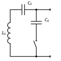
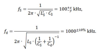
Figure 3: Receiver coil with dual resonant circuit
To tune the dual resonant circuit to the two resonance frequencies according to the Qi standard fs (100kHz) and fd (1000kHz), the values Ls and Ls' of the coil must be determined.
The self-inductance Ls can be taken from the receiver coil datasheet or determined at 100 kHz using a suitable measurement method.
The inductance Ls' is determined by positioning the receiver coil, ideally in a fully assembled state, including all relevant components such as PCB (PCBA), battery, and housing, centrically on a Qi transmitter pad (Figure 4). The distance between coil and transmitter should comply with exact specifications to ensure realistic coupling conditions. Subsequently, Ls' can be determined at 100 kHz using a suitable measurement method.
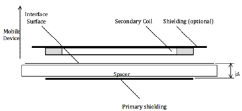
Figure 4: Measurement setup for determining inductance Ls'
Using the determined values of Ls and Ls', the series (CS) and parallel capacitor (Cd) can then be calculated using the formulas from Figure 3.
(Source: Qi-v1.3-power-delivery.pdf, 3.1 Dual resonant circuit)
Foreign Object Detection (FOD) – Safety and Certification
Since transmitter and receiver are physically separate devices, there is the possibility that foreign metallic objects such as coins or keys may unintentionally be located in the magnetic field between both components. Qi-based wireless charging systems have foreign object detection (FOD) for this purpose. Foreign object detection prevents heating of unwanted metal objects in the transmitter's magnetic field and thus potential fire hazards.
Furthermore, precise power regulation is enabled and ensures that the receiver complies with Qi specifications and can work with various Qi-compatible transmitters.
The calibration process includes the following steps:
- Measurement of received power with ideal coupling of both devices.
- Loss calculation: Losses outside the receiver, such as in the receiving coil and RF shielding
- FOD parameter adjustment: FOD parameters are adjusted to compensate for losses. This includes setting a fixed base value (offset) and a variable component (gain).
- Depending on the IC manufacturer, FOD calibration can be set via register values in the receiver or hardware-side via external resistors.
Our tip:
Use a calibrated test transmitter from the beginning. This increases the probability of passing Qi certification on the first attempt.
Since pre-compliance tests with certified test systems can also be cost-intensive, it is advisable to rely on calibrated test equipment from the start. This increases the probability of passing Qi certification on the first attempt. An established provider of Qi test systems is, for example, the company Nok9 (https://www.nok9.com/), whose devices are used in many certified test laboratories worldwide.
Your Roadmap to Qi Certification
Requirements for Qi certification:
Organizational:
- Membership in the Wireless Power Consortium (WPC)
- Product conformity: The product must be fully compatible with the current Qi specification.
Technical tests in authorized laboratory (e.g., Cetecom https://cetecomadvanced.com/de/testen/drahtlose-energieuebertragung/):
- Radio: ETSI EN 303 417
- EMC: EN 301 489-1 & -3
- Electrical safety based on standards EN 62311 or EN 62368 required
Interoperability test:
- The product is tested with a variety of already certified Qi devices for quality assurance.
Final steps:
- Submission of test results to WPC
- Product inclusion in the official Qi database
- Only then may the Qi logo be displayed on the product.
Summary of Key Points in Qi Receiver Development
Phase 1: Fundamentals
- Define standards and certification requirements
- Early coordination with test laboratory
- Procure calibrated test equipment
Phase 2: Design
- Define power profile
- Non-metallic housing (at least in the coil area)
- Coil selection and positioning
- Follow IC manufacturer design guidelines
Phase 3: Optimization
- Tune receiver coil
- Calibrate FOD
- Tests with Qi-certified charging pads
- Measure efficiency, temperature, and charging times
Phase 4: Validation
- Informal measurements at test laboratory
- Finalize design
- Regulatory testing (EMC, radio, safety)
- WPC certification
Conclusion: Qi Success Through Systematic Approach
Developing a Qi receiver product requires careful planning and coordination of various components to ensure efficient and reliable wireless energy transfer.
Important aspects include selecting the receiver coil and its positioning in the housing, adjusting the resonance capacitances, and implementing foreign object detection (FOD). Through integration of current standards such as Qi, developers have the opportunity to create powerful and user-friendly products.
Sources and References
Information on Qi Specifications
Information on Qi Certification
Knowledge Database

Adrian Sallaz
MSc in Biomedical Engineering, University of Bern and Bern University of Applied Sciences
Hardware and Embedded Software Engineer
About the author
Adrian Sallaz has been working as an Embedded Hardware & Software Engineer at CSA Engineering AG for nearly five years. His focus lies on developing customer-specific hardware designs.
His expertise has been instrumental in various projects for fine-tuning radio transmission to achieve optimal performance.