QR codes on ARM microcontrollers
QR codes have become hugely popular in recent years and are now used almost everywhere. They make it possible to display a large amount of information in a very compact form factor. Microcontrollers can be used to generate QR codes, which can then be displayed and scanned using a camera. Potential applications include identifying IoT devices and providing (interactive) information.
Content
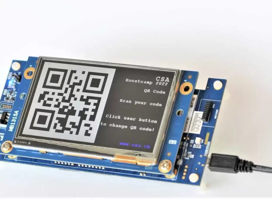
During Boostcamp 2022, we developed our expertise in various technologies, including QR codes. This involved creating an implementation example for displaying and scanning a QR code using an STM32H7B3I-DK Discovery Kit from ST. The Discovery Kit has a display that was used to show a QR code.
What is a QR code?
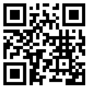
A QR code is a two-dimensional version of a barcode. It makes it possible to present a large amount of information in a very small format consisting of a two-dimensional matrix of black and white squares.
QR codes are standardised in accordance with the ISO 18004 standard. The standard distinguishes between 40 different versions. The version determines the number of pixels in the code, which can range from 21x21 to 177x177.
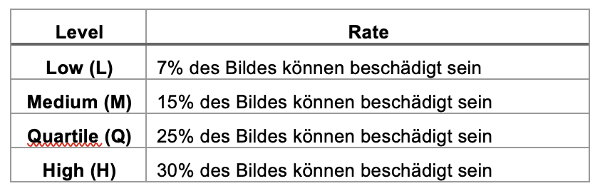
In addition to the different versions, there are four error correction levels. Depending on the level selected, 7% to 30% of the QR code data can be recovered by the Reed-Solomon code. The following error correction levels have been set:
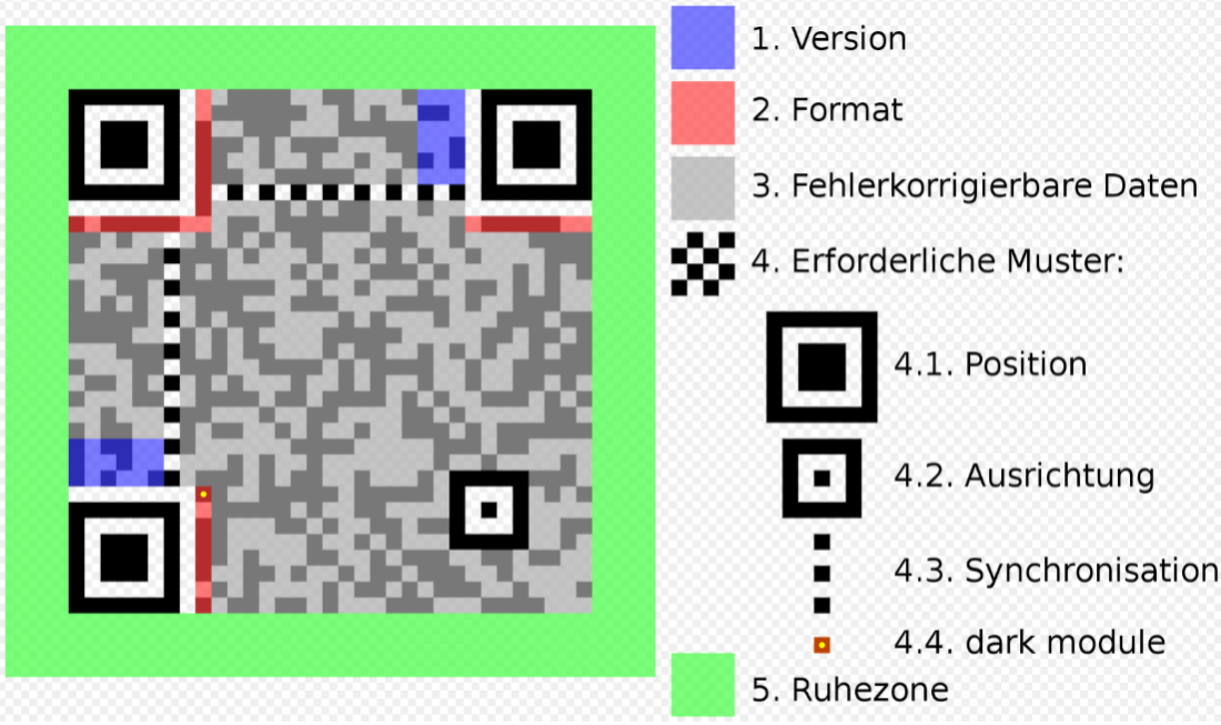
The structure of a QR code
Specific features:
- Version fields for determining the QR code version (1)
- Format fields with information on error tolerance and data mask (2)
- Data field and error correction data (3)
- Position markings in the corners (4.1)
- Alignment markings (smaller than position markings; these help with processing) (4.2)
- Timing lines for determining the size of the data matrix (4.3)
- Bit to represent the dark colour, also called “dark module” (4.4)
- Quiet zone (usually a white border for clear contrast) (5)
QR code generation and decryption in our application example
In the example we developed, any text can be presented in the form of a QR code on the display on the STM32H7B3I-DK Discovery Kit. The generated code has the following features:
- Selectable QR code version
- Configurable error correction level
- Output of the generated QR code as a 2D bit matrix
For decryption, any bit matrix (version, error correction level) can be interpreted and output as a string for further processing.
Implementation
As a basis, we chose a sample program for using the display from the STM32Cube IDE. To create the QR codes, we integrated an external C library into the project. The library converts a string into a one-dimensional bit array at the desired error correction level. Using a developed wrapper, the bit array was converted into a two-dimensional array and presented in the largest possible format on the display.
We used a C++ library to decrypt the QR code. To do this, the example project had to be adapted so that C++ code could also be compiled and executed.
The previously generated matrix was used as input for decryption and decrypted using the C++ library. This resulted in a string that matched the initial information provided. This was in turn shown on the display in the form of a text string.
Conclusion
By using the two libraries, we were able to implement the QR code functionality quickly and easily on the microcontroller. However, one sticking point for real-world application remains unresolved: integrating a camera and the image processing required to convert the live image into a bit matrix.