
Functional Safety according to IEC61508
«The software does what it is supposed to do.» This statement is often used as an argument in various contexts. However, despite the omnipresence of software systems, there is still no way to prove that software works without errors. This would be particularly useful in safety-critical applications and would significantly simplify verification.
To simplify verification and at the same time ensure functional safety, there are numerous standards.
The basic standard for functional safety is IEC 61508, from which various industry-specific standards have been derived.
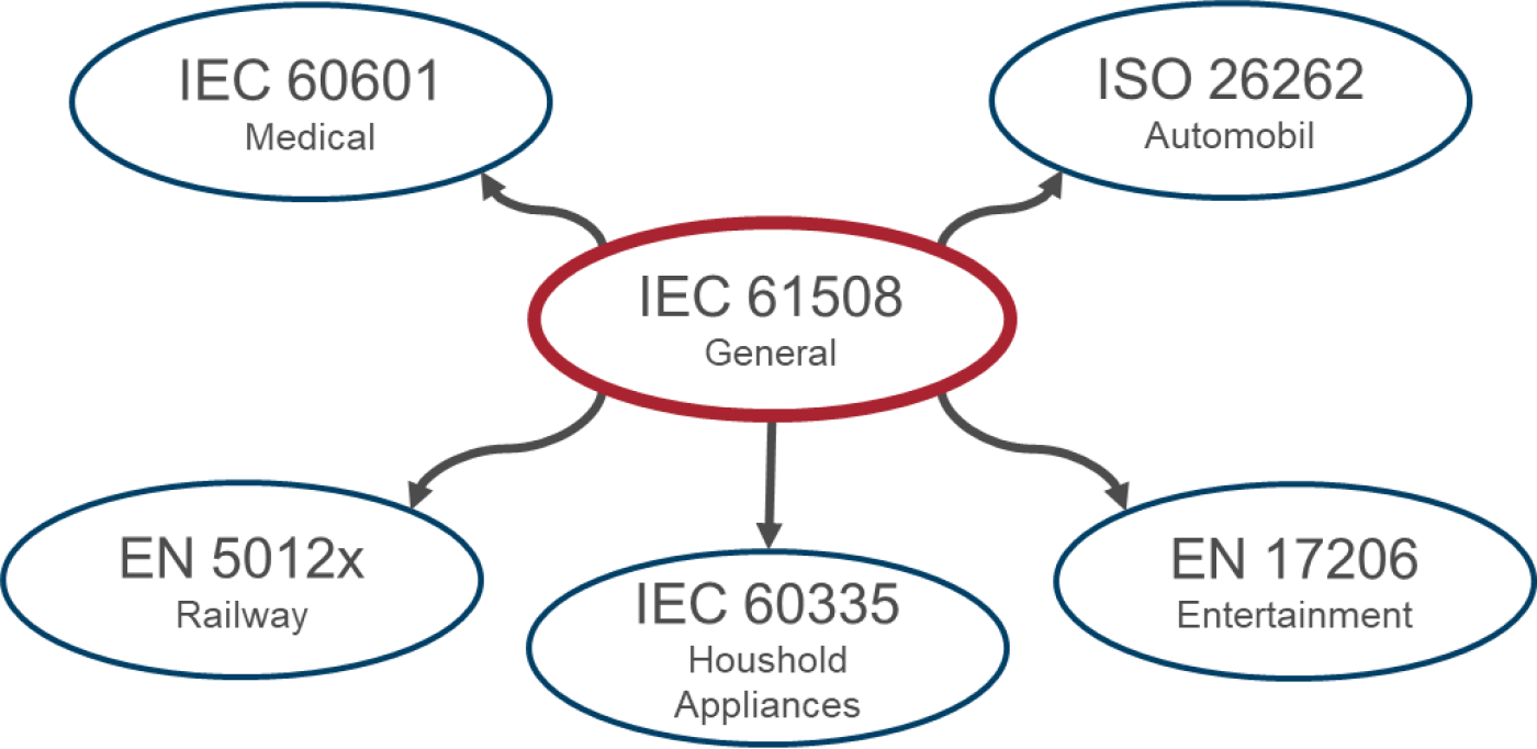
Figure 1: Standards landscape functional safety (excerpt)
Safety and Security
In German, the word Sicherheit (safety/security) is ambiguous. To avoid misunderstandings, the English terms Security and Safety are often used.
Security refers to ensuring the confidentiality of data of a system or individuals. Primarily, it is about protecting the system from an individual.
Safety, on the other hand, according to IEC 61508, refers to the acceptable risk of a system in terms of protecting health, the environment, and the system itself. It is therefore about protecting an individual from the system.
Once safety has been implemented, the system can be considered functionally safe. In contrast, security is subject to the fast pace of the technologies used. Measures that have already been taken may no longer be sufficient after some time.
This blog focuses on functional safety, i.e. Safety.
Why is functional safety needed?
The maiden flight of the Ariane 5 rocket on June 4, 1996 fell victim to a software error. After 37 seconds, the onboard computer decided on a major course correction. Due to the strong forces of air resistance, the rocket eventually broke apart and triggered the self-destruct mechanism provided for in this case.
Investigations revealed that the code for calibrating the inertial navigation platforms was faulty before launch. This code had been blindly adopted from the predecessor model, the Ariane 4, and continued running for 40 seconds after launch.
For the Ariane 5, this continuation was unnecessary or the time was far too long. As it had significantly more thrust and agility than its predecessor, this led to an overflow in the attitude estimation. As a result, the onboard computer received neither sensor data nor calculated attitude data, only diagnostic data. However, the onboard computer interpreted this as normal flight data.
Several errors were made, each of which would have prevented destruction if it had not occurred:
- If the requirements for the adopted code had been checked, it would have been noticed that continuing for 40 seconds was unnecessary.
- If the code had not been adopted untested, a possible overflow would have been discovered during tests. Tests with Ariane 5 flight data were cut for cost reasons.
- If appropriate exception handling for an overflow had been in place, forwarding of attitude and sensor data would have been ensured.
It is therefore clear that in a development process designed for functional safety, this error would not have gone undetected.
This is where IEC61508 comes in. The standard specifies a safety lifecycle, which defines requirements for the development process of hardware and software products. This is intended to identify and eliminate errors, such as in the Ariane 5 example, at an early stage.
Functional safety thus serves to protect people and machines. To quantify this safety, the following terms are defined:
- Safety: Freedom from unacceptable risks
- Risk: Combination of probability of occurrence and severity of damage
- Hazard: Potential source of damage
The goal is to reduce the risk to an acceptable level.
Development process according to IEC61508
The standard strongly recommends development according to the V-model. As a central element, the risk analysis stands at the beginning. Based on this, the concept phase starts, followed by the realization phase. Figure 2 shows the different stages.
The phases after development are also shown, namely installation, operation, modification, and decommissioning, for which the standard also specifies steps to be taken into account.
Looking at each phase in detail would go beyond the scope of this blog post. For this reason, the focus here is on risk analysis and realization in hardware and software.
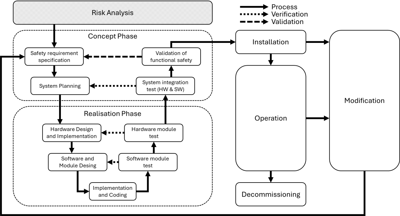
Figure 2: Development process according to IEC61508
Risk analysis
IEC61508 defines four Safety Integrity Levels (SIL). The categorization describes the required level of risk reduction, with SIL1 indicating the lowest and SIL4 the highest risk reduction. Risks are identified through risk analysis, from which the required SIL is derived.
By the way, a risk analysis is also required for non-safety-critical applications as part of CE approval.
To conduct a risk analysis, the standard defines in part 5 different methods:
- The ALARP method (As Low As Reasonably Practicable)
- The quantitative method of SIL determination
- The risk graph method
- Layer of Protection Analysis (LOPA)
- Matrix of the extent of the hazardous event
Each method has its own areas of application and can complement one another. The following section explains the risk graph method in more detail, which is often applied in various projects.
The Risk Graph Method
This method introduces a number of parameters that can describe a hazard if safety systems fail or are not present.
C: Consequence of the event
F: Frequency of exposure
P: Possibility of avoiding the event
W: Probability of the undesired event occurring
The classifications can, for example, be defined as follows:
| Parameter | Classification |
|---|---|
| C1 | Minor injury |
| C2 | Serious, irreversible injury to one or more persons; death of one person |
| C3 | Death of several people |
| C4 | Death of many people |
| F1 | Rare to frequent presence in the hazardous area |
| F2 | Frequent to continuous presence in the hazardous area |
| P1 | Possibility, under certain conditions, of avoiding the hazardous event |
| P2 | Almost impossible to avoid the hazardous event |
| W1 | Low probability that the undesired event will occur |
| W2 | High probability that the undesired event will occur |
Table 1: Possible classification of risk graph parameters
After this, a risk graph can be drawn and for a range of hazardous incidents the parameters can be classified. The required SIL level results in order to reduce the risk sufficiently so that the system can be operated in a functionally safe manner.
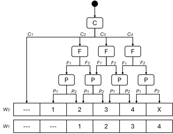
Figure 3: Possible risk graph for determining the SIL
--- = no safety requirements
1-4 = SIL
X = several SIL4 safety functions are required
Safety function and error types
For further analysis and implementation, the standard defines some key terms.
A safety function is a function performed by a system to minimize risks. The goal is to achieve a safe state for the system when a predefined hazardous event is considered.
A safety function always includes the following subsystems:
- One or more sensors
- Logic
- One or more actuators
The safety function should detect errors and transfer the system to a safe state. In this state, it is guaranteed that the system does not cause a hazardous incident. Depending on the system and the safety function, however, it may also mean that it is no longer available for normal operation and must be serviced, repaired, or reset.
The IEC61508 distinguishes between two types of errors: random and systematic errors.
Systematic errors occur due to incorrect design. In hardware, this could occur, for example, by operating components outside their specification. In software, a coding error is present. Software errors are always systematic errors. Systematic errors should be avoided with a good development process and appropriate techniques and measures. The standard includes recommendations and requirements on which measures are considered appropriate in each case.
Random errors occur despite correct design, cannot be predicted, but can be described statistically. An example would be a component that shows a short circuit after reaching its maximum service life. Random errors should be controlled at runtime by redundancy, diversification, or self-tests.
It is important to think carefully about possible failures and their effects. One tool for this is FMEA (Failure Mode and Effect Analysis). In simple terms, each component (hardware and software) is examined for possible failures, and the effects of a failure are assessed in terms of severity, frequency, and possibility of detection. The result is a table that allows prioritization of failures and shows where the most critical components in the system are.
Implementation
When implementing safety functions, IEC61508 provides numerous tools to select appropriate measures. This applies both to handling random errors at runtime and to avoiding systematic errors during development.
Random errors can, for example, be reduced by lowering the operating values of components. If a resistor is designed for operation at 10A, it should nevertheless only be operated at a maximum of 6.5A. On the one hand, this creates a safety margin to absorb short peaks, and on the other hand, it increases the service life since the resistor becomes less hot and therefore wears less over time.
Another possibility is to introduce components redundantly. A majority voter determines how much tolerance is allowed in the values of the redundant paths. Diversification across several technologies is also a good way to detect and reduce random errors.
Systematic errors are avoided by a robust process. This includes structured design, modularization (hardware and software), and verification through reviews and tests. Writing requirements also contributes significantly to preventing misunderstandings. If a requirement is clear, precise, and unambiguous, it is easier for everyone involved to develop a good system.
The standard also specifies measures for writing safe code. Readability, testability, adherence to coding guidelines (conventions, structure, documentation) and coding rules (e.g. MISRA), and verification of compliance with these rules using automated analysis tools are just some of them.
Example: Elevator doors
In an example, various aspects of the development process will be illustrated. A safety system for elevator doors is to be developed. Initially, it is assumed that the system has no safety functions. When the button is pressed, the doors open.
SIL determination using risk graph
The risk graph method presented in the chapter "The risk graph method" is applied.
1) Identify hazardous incidents
- Shaft door opens although the cabin is not present
- Elevator door traps a person
- Elevator starts moving with the door open
2) C: Consequence of an incident
- Fall and thus serious injury or death of a person -> C2
3) F: Frequency of the incident
- Frequent entering or leaving of people -> F2
4) P: Possibility of avoiding the incident
- Almost impossible when the cabin is in motion -> P2
5) W: Probability
- High probability -> W2
Following the risk graph shown in Figure 3 results in the following: The risk is not acceptable and must be reduced with a safety function at SIL3.
Design of a safety function
A simple safety function for elevator doors could be monitoring the status of the doors. A limit switch indicates whether the door is open or closed (sensor), a microcontroller evaluates the data from the limit switch (logic), and prevents the cabin from moving by blocking it with a bolt (actuator).
The bolt is only retracted when the limit switch indicates that the doors are fully closed. This prevents the elevator from starting with open doors.
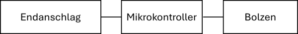
Figure 4: Simple safety function
However, this function does not prevent the shaft doors from opening without the cabin being present. Another safety function would be needed for this.
For example: A proximity sensor detects the presence of the cabin. A microcontroller evaluates the sensor data and releases the power supply of the door motors.
If the control system erroneously wants to open the door motors, it cannot do so because the safety function does not release the voltage to the motors.
Simple FMEA for the safety function
For the safety function described above, a simple table for the limit switch is created.
| Component | Failure mode | Effect | Severity | Frequency | Detection | Risk prioritization |
|---|---|---|---|---|---|---|
| Limit switch | Always reports door open | Elevator cannot start | 1 | 3 | 10 | 1 * 3 * 10 = 30 |
| Limit switch | Always reports door closed | Elevator can start with open door | 7 | 3 | 10 | 7 * 3 * 10 = 210 |
Table 2: Strongly simplified FMEA for the limit switch
The severity shows that a limit switch that always reports a closed door is much more dangerous than one that always reports an open door and therefore needs to be prioritized higher.
Diversification for the limit switch
In the FMEA, a hazardous failure mode was identified for the limit switch. By using different technologies for measuring the state of the elevator door, the risk of an open door is minimized.
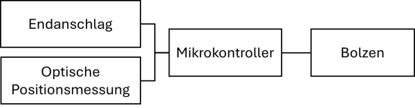
Figure 5: Safety function with diversification
Conclusion
As the Ariane 5 rocket story or the fictional elevator example shows, functional safety is in many cases of great importance for the safe use of systems. Developing such systems is not trivial, but there are tools to help. The IEC61508 basic standard provides structure, procedure, and concrete measures to reduce risks to an acceptable level. Knowledge in this area directly helps to select the appropriate approach and measures and simplifies development.
CSA Engineering AG has this know-how and experience in dealing with the IEC61508 standard and its derived standards. We are happy to support you in the conception, development, or verification of safe systems, whether in industrial automation, medical technology, or railway technology.

Mathieu Bourquin
BSc BFH in Electrical and Communication Engineering
Embedded Software Engineer
Über den Autor
Mathieu Bourquin has been working as an Embedded Software Engineer at CSA for four years. He supports customers in the medical technology sector and is a specialist in developing firmware in C/C++ as well as in the implementation of functional safety (Functional Safety Certified Engineer – TÜV Süd).